NASA GSFC requested STi to review the EO-1 WARP Low-Voltage Power Converter (LVPC) Assembly because of problems during testing. A worst-case electrical parts stress analysis and related design analysis were conducted. These tasks were performed on the EO-1 WARP Low-Voltage Power Converter (LVPC) Assembly Main Board and Control Board. A performance assessment of the LVPC under worse-case condition was conducted to verify the performance of the circuit and the robustness of the design.
The first analysis was a part stress analysis performed under worst-case conditions for the entire design. This analysis yielded 30 components that exceeded derated maximum stress as specified in PPL-21. Out of 30 parts identified, 17 are remaining as significant concerns, which required further analysis taking into account measured data from the flight unit. 8 of these 17 parts are tantalum capacitors with possible ripple current overstress; the remaining 9 parts of concern are switching transistors which may see transient spikes that exceed derating requirements. (Q408 – Q410 are 60V-rated for collector-emitter voltage; the rest are 100V-rated.) Each component is noted in one of the concerns below. Table 1 shows the breakdown by part type.
Table 1 – Potentially Overstressed Parts Statistics
| Type of Component |
Parts Analyzed
|
Parts Exceed Derating (W/C)
|
Overstressed Parts (W/C)
|
| Resistors |
262
|
7
|
0
|
| Capacitors |
220
|
12
|
10
|
| Diodes |
87
|
0
|
0
|
| Transistors |
19
|
9
|
0
|
| Linear Microcircuits |
30
|
0
|
0
|
| Digital Microcircuits |
10
|
0
|
0
|
| Transformers/Inductors |
49
|
2
|
2
|
| TOTAL |
677
|
30
|
12
|
The remainder of the EO-1 WARP LVPC passes the stress analysis under worst-case conditions, and is unlikely to experience overstress during the mission.
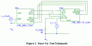
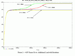
The performance verification of the start-up circuit under worst-case conditions revieled that the circuit will not start up properly under worst-case conditions. Figure-1 represents performance verification test circuit. STi determined it necessary to utilize PSpice modeling and simulation for this effort to obtain an accurate verification of the performance of the entire circuit. Figure-2 verifies the design has the current margins of 1.92mA. If the current margins exceeds 1.94mA the Start-up circuit will not start properly resulting in the start up anomaly.


